The Review of wiringPi
Intro
Logic gate and Bit operation were reviewed for wiringpi code analysis.
This document starts code analysis based on Raspberry Pi4 .
Once the code analysis is complete, proceed to the application case.
The target is the odroid-wiringpi that I ported directly to the odroid.
It is assumed that the person looking at this document can understand the datasheet
and has a good understanding of C/C++ and bit operations.
Requirements
Prepare what you need when analyzing the code.
It’s a optional to be prepared, but I still recommend you to be prepared.
target

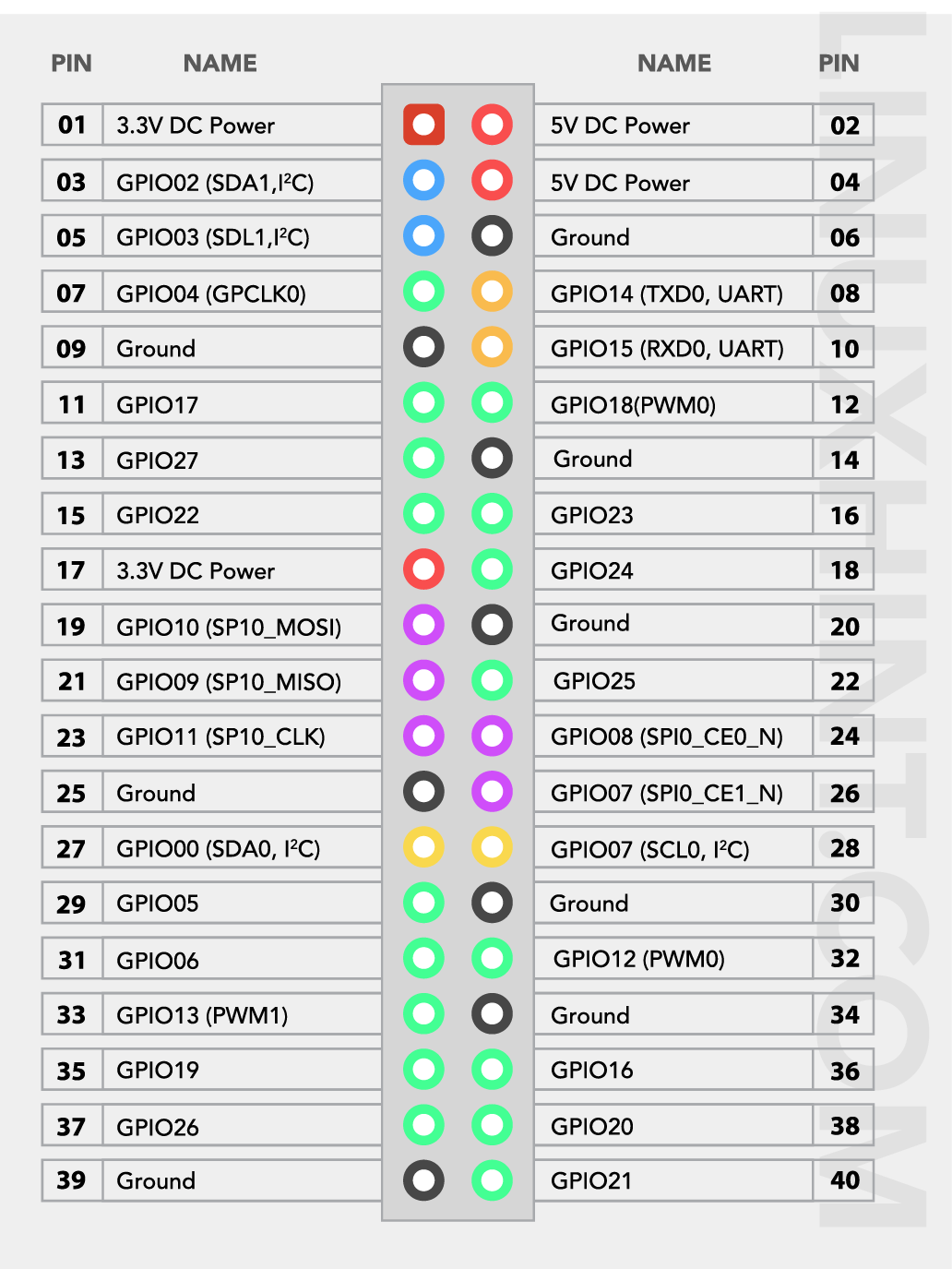
Raspberry Pi 4 & gpio header
datasheet
GPIO control is a method of directly accessing memory addresses and entering values into registers.
After accessing memory addresses through memory mapping, control gpio with bit operations.
source code
$ git clone https://github.com/WiringPi/WiringPi.git
Code Review
As I mentioned above, it goes on the assumption that you can understand C/C++ and read data sheet to some extent.
WiringPi also supports extension pins with wiringPiNodeStruct ,
But this document covers only the on-board case.
wiringPiSetup
wiringPiSetup uses mmap to map memory.
Memory mapping(using mmap) must precede access to the GPIO register.
Check the model first and attach the correct memory address for the model.
Usage:
#include <wiringPi.h>

int main()
{
  wiringPiSetup();

  return 0;
}
piBoardId, wiringPiSetup
code: wiringPi/wiringPi.c
void piBoardId (int *model, int *rev, int *mem, int *maker, int *warranty)
{
  FILE *cpuFd ;
  char line [120] ;
  char *c ;
  unsigned int revision ;
  int bRev, bType, bProc, bMfg, bMem, bWarranty ;

//  Will deal with the properly later on - for now, lets just get it going...
//  unsigned int modelNum ;

  (void)piGpioLayout () ;   // Call this first to make sure all's OK. Don't care about the result.

  if ((cpuFd = fopen ("/proc/cpuinfo", "r")) == NULL)
    piGpioLayoutOops ("Unable to open /proc/cpuinfo") ;

...

}
int wiringPiSetup (void)
{
  int   fd ;
  int   model, rev, mem, maker, overVolted ;

  if (wiringPiSetuped)
    return 0 ;

  ...

  piBoardId (&model, &rev, &mem, &maker, &overVolted) ;

  ...

  switch (model)
  {
    case PI_MODEL_A:    case PI_MODEL_B:
    case PI_MODEL_AP:   case PI_MODEL_BP:
    case PI_ALPHA:  case PI_MODEL_CM:
    case PI_MODEL_ZERO: case PI_MODEL_ZERO_W:
      piGpioBase = GPIO_PERI_BASE_OLD ;
      piGpioPupOffset = GPPUD ;
      break ;

    case PI_MODEL_4B:
    case PI_MODEL_400:
    case PI_MODEL_CM4:
      piGpioBase = GPIO_PERI_BASE_2711 ;
      piGpioPupOffset = GPPUPPDN0 ;
      break ;

    default:
      piGpioBase = GPIO_PERI_BASE_2835 ;
      piGpioPupOffset = GPPUD ;
      break ;
  }

  ...

  if ((fd = open ("/dev/mem", O_RDWR | O_SYNC | O_CLOEXEC)) < 0)
  {
    if ((fd = open ("/dev/gpiomem", O_RDWR | O_SYNC | O_CLOEXEC) ) >= 0)    // We're using gpiomem
    {
      piGpioBase   = 0 ;
      usingGpioMem = TRUE ;
    }
    else
      return wiringPiFailure (WPI_ALMOST, "wiringPiSetup: Unable to open /dev/mem or /dev/gpiomem: %s.\n"
    "  Aborting your program because if it can not access the GPIO\n"
    "  hardware then it most certianly won't work\n"
    "  Try running with sudo?\n", strerror (errno)) ;
  }

// Set the offsets into the memory interface.

  GPIO_PADS       = piGpioBase + 0x00100000 ;
  GPIO_CLOCK_BASE = piGpioBase + 0x00101000 ;
  GPIO_BASE   = piGpioBase + 0x00200000 ;
  GPIO_TIMER      = piGpioBase + 0x0000B000 ;
  GPIO_PWM    = piGpioBase + 0x0020C000 ;

...

  //  GPIO:

    gpio = (uint32_t *)mmap(0, BLOCK_SIZE, PROT_READ|PROT_WRITE, MAP_SHARED, fd, GPIO_BASE) ;
    if (gpio == MAP_FAILED)
      return wiringPiFailure (WPI_ALMOST, "wiringPiSetup: mmap (GPIO) failed: %s\n", strerror (errno)) ;

  //  PWM

    pwm = (uint32_t *)mmap(0, BLOCK_SIZE, PROT_READ|PROT_WRITE, MAP_SHARED, fd, GPIO_PWM) ;
    if (pwm == MAP_FAILED)
      return wiringPiFailure (WPI_ALMOST, "wiringPiSetup: mmap (PWM) failed: %s\n", strerror (errno)) ;

  //  Clock control (needed for PWM)

    clk = (uint32_t *)mmap(0, BLOCK_SIZE, PROT_READ|PROT_WRITE, MAP_SHARED, fd, GPIO_CLOCK_BASE) ;
    if (clk == MAP_FAILED)
      return wiringPiFailure (WPI_ALMOST, "wiringPiSetup: mmap (CLOCK) failed: %s\n", strerror (errno)) ;

  //  The drive pads

    pads = (uint32_t *)mmap(0, BLOCK_SIZE, PROT_READ|PROT_WRITE, MAP_SHARED, fd, GPIO_PADS) ;
    if (pads == MAP_FAILED)
      return wiringPiFailure (WPI_ALMOST, "wiringPiSetup: mmap (PADS) failed: %s\n", strerror (errno)) ;

  //  The system timer

    timer = (uint32_t *)mmap(0, BLOCK_SIZE, PROT_READ|PROT_WRITE, MAP_SHARED, fd, GPIO_TIMER) ;
    if (timer == MAP_FAILED)
      return wiringPiFailure (WPI_ALMOST, "wiringPiSetup: mmap (TIMER) failed: %s\n", strerror (errno)) ;

  // Set the timer to free-running, 1MHz.
  //  0xF9 is 249, the timer divide is base clock / (divide+1)
  //  so base clock is 250MHz / 250 = 1MHz.

    *(timer + TIMER_CONTROL) = 0x0000280 ;
    *(timer + TIMER_PRE_DIV) = 0x00000F9 ;
    timerIrqRaw = timer + TIMER_IRQ_RAW ;

  // Export the base addresses for any external software that might need them

    _wiringPiGpio  = gpio ;
    _wiringPiPwm   = pwm ;
    _wiringPiClk   = clk ;
    _wiringPiPads  = pads ;
    _wiringPiTimer = timer ;

...
The part of the function associated with memory mapping.
You can see that wiringPiSetup is trying to map memory using the /dev/mem and mmap functions.
First, check the gpio only.
look at the specific binary values of gpio,
#define BLOCK_SIZE (4*1024)
...

GPIO_BASE = piGpioBase + 0x00200000;

...

#define GPIO_PERI_BASE_2711 0xFE000000

...
Now let’s find out what this value means in the data sheet.
At page 66,

[picture 2] gpio_base
But look at the code, it’s 0xFE200000, not 0x7e200000. Let’s find the reason.
At page 5,
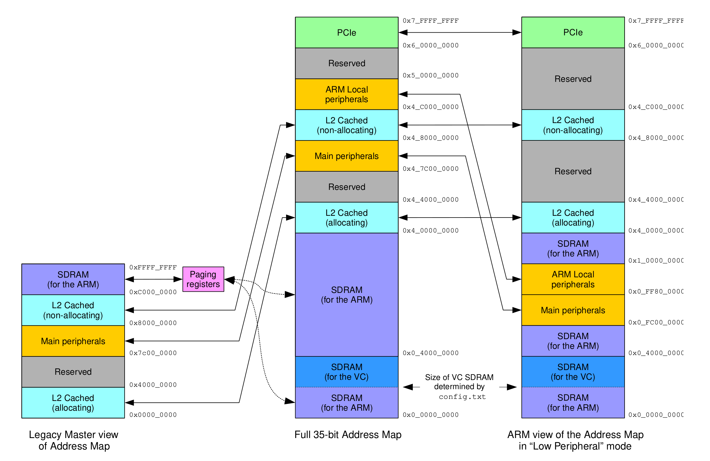
[picture 3] address_maps
0x7e200000 is based on a Legacy Master view of Address Map.
It belongs to the ‘Main peripherals’ area. If you follow the address map with the same offset
0xFE200000 is based on “Low Peripheral” mode.
I don’t know why, but from now on, we will follow the address system based on ‘Low Peripheral’ mode.
mmap code
  //  GPIO:

    gpio = (uint32_t *)mmap(0, BLOCK_SIZE, PROT_READ|PROT_WRITE, MAP_SHARED, fd, GPIO_BASE) ;
    if (gpio == MAP_FAILED)
      return wiringPiFailure (WPI_ALMOST, "wiringPiSetup: mmap (GPIO) failed: %s\n", strerror (errno)) ;
...

    _wiringPiGpio  = gpio ;

...
mmap form
#include <sys/mman.h>

void *mmap(void *start, size_t length, int prot, int flags, int fd, off_t offset);
I don’t cover on mmap because we assume that you have a good understanding in advance
But I mention the important part.
size_t length indicates the mapping size unit.
The length is BLOCK_SIZE , The address to be mapped must be a multiple of BLOCK_SIZE.
Our case has GPIO_BASE of 0xFE200000, so there is no problem.
Otherwise, however, you must force the base-address to be a multiple of the nearest BLOCK_SIZE .
and add or subtract the offset value to add to the bit operation accordingly.
These cases can be found in odroid-wiringpi: ODROID-C4 .
Anyway, It used mmap to map the gpio variable to the 0xFE200000 .
pinMode
After wiringPiSetup, define pin using pinMode .
Usage
#include <wiringPi.h>

int main()
{
  wiringPiSetup();
  pinMode(0, INPUT);
  pinMode(1, OUTPUT);

  return 0;
}
pinMode
code: wiringPi/wiringPi.c
void pinMode (int pin, int mode)
{
  int    fSel, shift, alt ;
  struct wiringPiNodeStruct *node = wiringPiNodes ;
  int origPin = pin ;

  setupCheck ("pinMode") ;

  if ((pin & PI_GPIO_MASK) == 0)        // On-board pin
  {
    /**/ if (wiringPiMode == WPI_MODE_PINS)
    pin = pinToGpio [pin] ;

    ...

    fSel    = gpioToGPFSEL [pin] ;
    shift   = gpioToShift  [pin] ;

    /**/ if (mode == INPUT)
      *(gpio + fSel) = (*(gpio + fSel) & ~(7 << shift)) ; // Sets bits to zero = input
    else if (mode == OUTPUT)
      *(gpio + fSel) = (*(gpio + fSel) & ~(7 << shift)) | (1 << shift) ;

    ...

    return ;
The input pin number is the wiringPi pin number and converts it into a hardware gpio number inside the function.
In other words, the wiringPi pin number and the hardware gpio pin number are connected.
See pinToGpio array.
pinToGpio
code: wiringPi/wiringPi.c
// in wiringPiSetup()

...

 /**/ if (piGpioLayout () == 1)    // A, B, Rev 1, 1.1
  {
     pinToGpio =  pinToGpioR1 ;
    physToGpio = physToGpioR1 ;
  }
  else                  // A2, B2, A+, B+, CM, Pi2, Pi3, Zero, Zero W, Zero 2 W
  {
     pinToGpio =  pinToGpioR2 ;
    physToGpio = physToGpioR2 ;
  }

...
static int pinToGpioR1 [64] =
{
  17, 18, 21, 22, 23, 24, 25, 4,    // From the Original Wiki - GPIO 0 through 7:   wpi  0 -  7
   0,  1,               // I2C  - SDA1, SCL1                wpi  8 -  9
   8,  7,               // SPI  - CE1, CE0              wpi 10 - 11
  10,  9, 11,               // SPI  - MOSI, MISO, SCLK          wpi 12 - 14
  14, 15,               // UART - Tx, Rx                wpi 15 - 16

// Padding:

      -1, -1, -1, -1, -1, -1, -1, -1, -1, -1, -1, -1, -1, -1, -1,   // ... 31
  -1, -1, -1, -1, -1, -1, -1, -1, -1, -1, -1, -1, -1, -1, -1, -1,   // ... 47
  -1, -1, -1, -1, -1, -1, -1, -1, -1, -1, -1, -1, -1, -1, -1, -1,   // ... 63
} ;

// Revision 2:

static int pinToGpioR2 [64] =
{
  17, 18, 27, 22, 23, 24, 25, 4,    // From the Original Wiki - GPIO 0 through 7:   wpi  0 -  7
   2,  3,               // I2C  - SDA0, SCL0                wpi  8 -  9
   8,  7,               // SPI  - CE1, CE0              wpi 10 - 11
  10,  9, 11,               // SPI  - MOSI, MISO, SCLK          wpi 12 - 14
  14, 15,               // UART - Tx, Rx                wpi 15 - 16
  28, 29, 30, 31,           // Rev 2: New GPIOs 8 though 11         wpi 17 - 20
   5,  6, 13, 19, 26,           // B+                       wpi 21, 22, 23, 24, 25
  12, 16, 20, 21,           // B+                       wpi 26, 27, 28, 29
   0,  1,               // B+                       wpi 30, 31

// Padding:

  -1, -1, -1, -1, -1, -1, -1, -1, -1, -1, -1, -1, -1, -1, -1, -1,   // ... 47
  -1, -1, -1, -1, -1, -1, -1, -1, -1, -1, -1, -1, -1, -1, -1, -1,   // ... 63
} ;
Depending on the return of piGpioLayout ,
an array of pinToGpioR1 or pinToGpioR2 is involved.
The index value of array is the pin number of wiringpi.
The values are written in the mapped gpio,
fsel, which is the register offset,
and shift, which is the bit shift value.
gpioToGPFSEL, gpioToShift
code: wiringPi/wiringPi.c
static uint8_t gpioToGPFSEL [] =
{
  0,0,0,0,0,0,0,0,0,0,
  1,1,1,1,1,1,1,1,1,1,
  2,2,2,2,2,2,2,2,2,2,
  3,3,3,3,3,3,3,3,3,3,
  4,4,4,4,4,4,4,4,4,4,
  5,5,5,5,5,5,5,5,5,5,
} ;


// gpioToShift
//  Define the shift up for the 3 bits per pin in each GPFSEL port

static uint8_t gpioToShift [] =
{
  0,3,6,9,12,15,18,21,24,27,
  0,3,6,9,12,15,18,21,24,27,
  0,3,6,9,12,15,18,21,24,27,
  0,3,6,9,12,15,18,21,24,27,
  0,3,6,9,12,15,18,21,24,27,
  0,3,6,9,12,15,18,21,24,27,
} ;
Find what these values mean.
At page 66,
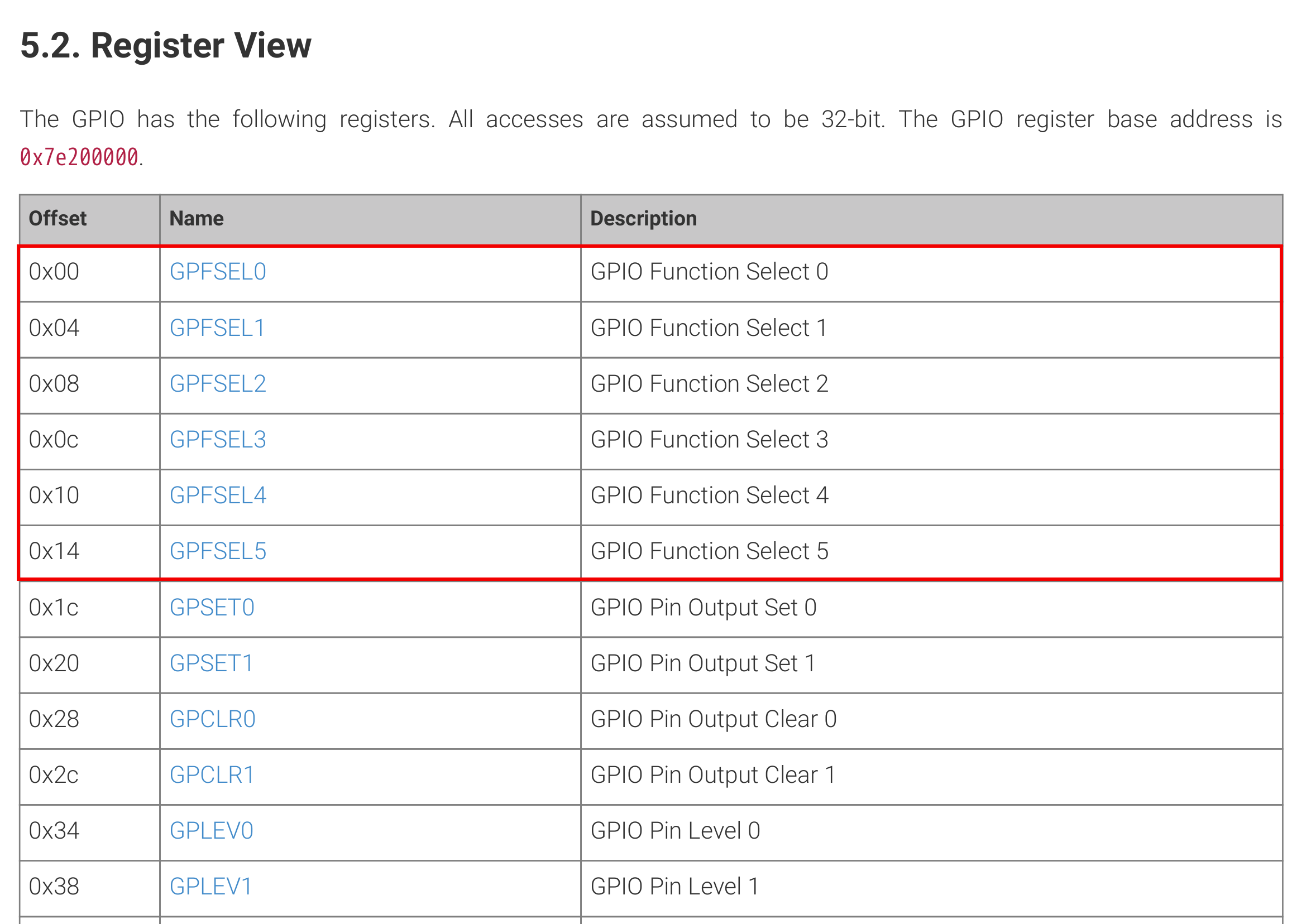
[picture 4] GPFSEL Maps
At page 67-70, (gpfsel0 register)
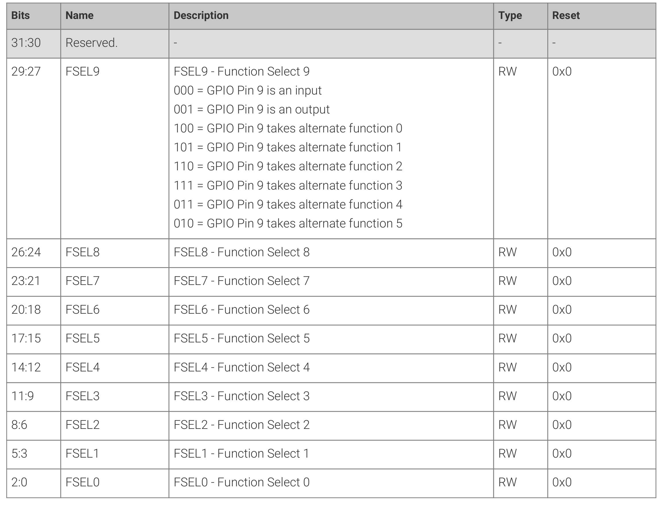
[picture 5] GPFSEL[n]
There are up to GPIO57 with the same rules.
And then look at the code again.
void pinMode (int pin, int mode)
{
  ...

  if ((pin & PI_GPIO_MASK) == 0)        // On-board pin
  {
    ...

    fSel    = gpioToGPFSEL [pin] ;
    shift   = gpioToShift  [pin] ;

    /**/ if (mode == INPUT)
      *(gpio + fSel) = (*(gpio + fSel) & ~(7 << shift)) ; // Sets bits to zero = input
    else if (mode == OUTPUT)
      *(gpio + fSel) = (*(gpio + fSel) & ~(7 << shift)) | (1 << shift) ;

    ...

    return ;
Isn’t something strange?
fSel offset are 0x0, 0x4 0x8 …
But, code is
| GPIO | fSel |
|---|---|
| 0 ~ 9 | 0 |
| 10 ~ 19 | 1 |
| 20 ~ 29 | 2 |
| 30 ~ 39 | 3 |
| 40 ~ 49 | 4 |
| 50 ~ 57 | 5 |
Because of the pointer operation rule in C .
The value added or subtracted from the pointer variable is calculated
by multiplying the value by the size of the pointer type, not by the value itself.
e.g.
int *foo = (int *)malloc(sizeof(int));

printf("*(foo) is 0x%x\n", *(foo));
printf("*(foo + 1) is 0x%x\n", *(foo + 1));
*(foo) is 0x00100000
*(foo + 1) is 0x00100004
It might be confusing if you play C after a long time.
pinMode
    /**/ if (mode == INPUT)
      *(gpio + fSel) = (*(gpio + fSel) & ~(7 << shift)) ; // Sets bits to zero = input
    else if (mode == OUTPUT)
      *(gpio + fSel) = (*(gpio + fSel) & ~(7 << shift)) | (1 << shift) ;
if pinMode:GPIO3, shift is 9.
(7 « shich) is 1110 0000 0000 .
This means that you will force the 9th to 11th bit digits to zero.
This part is covered in the bit operation part, so let’s move on.
digitalRead
Read the value of a given Pin, returning HIGH or LOW.
Usage: digitalRead(int pin)
#include <stdio.h>
#include <wiringPi.h>

int main()
{
  int val;

  wiringPiSetup();
  pinMode(0, INPUT);

  while (1) {
    val = digitalRead(0);
    printf("pin 0 status: %d\n", val);
    delay(500);
  }

  return 0;
}
digitalRead
code: wiringPi/wiringPi.c
int digitalRead (int pin)
{
  char c ;
  struct wiringPiNodeStruct *node = wiringPiNodes ;
  if ((pin & PI_GPIO_MASK) == 0)        // On-Board Pin
  {
    /**/ if (wiringPiMode == WPI_MODE_GPIO_SYS) // Sys mode
    {
      ...
    }

    else if (wiringPiMode == WPI_MODE_PINS)
      pin = pinToGpio [pin] ;
    else if (wiringPiMode == WPI_MODE_PHYS)
      pin = physToGpio [pin] ;
    else if (wiringPiMode != WPI_MODE_GPIO)
      return LOW ;
    if ((*(gpio + gpioToGPLEV [pin]) & (1 << (pin & 31))) != 0)
      return HIGH ;
    else
      return LOW ;
  }
  else
  {
    if ((node = wiringPiFindNode (pin)) == NULL)
      return LOW ;
    return node->digitalRead (node, pin) ;
  }
}
gpioToGPLEV
code: wiringPi/wiringPi.c
// gpioToGPLEV:
//  (Word) offset to the GPIO Input level registers for each GPIO pin

static uint8_t gpioToGPLEV [] =
{
  13,13,13,13,13,13,13,13,13,13,13,13,13,13,13,13,13,13,13,13,13,13,13,13,13,13,13,13,13,13,13,13,
  14,14,14,14,14,14,14,14,14,14,14,14,14,14,14,14,14,14,14,14,14,14,14,14,14,14,14,14,14,14,14,14,
} ;
| GPIO | gpioToGPLEV |
|---|---|
| 0 ~ 31 | 13 |
| 32 ~ 63 | 14 |
gpioToGPLEV is the offset.
Let’s go over the datasheet again.
A register indicating the gpio level is here.
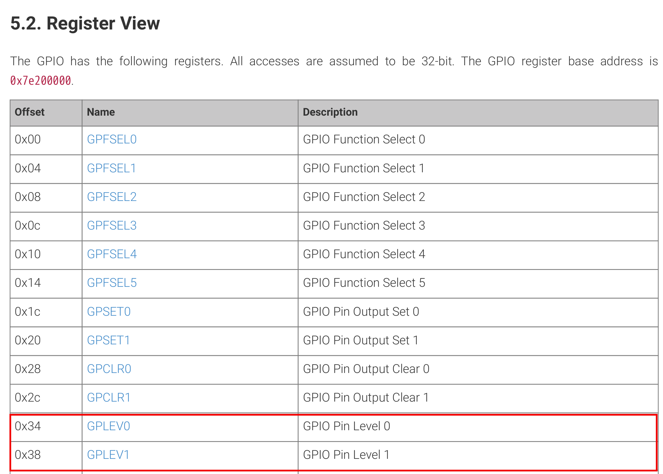
[picture 6] GPLEV offset[n]
The addresses match considering the nature of the pointer operation.
(0xD)*4 = 0x34, (0xE)*4 = 0x38
The description of GPLEV is here.

[picture 7] GPLEV description
In digitalRead ,
    if ((*(gpio + gpioToGPLEV [pin]) & (1 << (pin & 31))) != 0)$
      return HIGH ;$
    else$
      return LOW ;$
You can see two things.
Determining HIGH/LOW by using the & operation
And the ‘&’ operation limits the pin maximum to 31.
This is because the & operation forces the conversion of all digits with zero to zero based on the operand that follows.
digitalWrite
As the review progresses, there is less content to deal with.
Because the code proceeds in the same way.
Usage: digitalWrite(int pin, int value)
#include <stdio.h>
#include <wiringPi.h>

int main()
{ // connect wpi 0 and wpi 1.
  int val;

  wiringPiSetup();
  pinMode(0, INPUT);
  pinMode(1, OUTPUT);

  while (1) {
    digitalWrite(1, HIGH);
    val = digitalRead(0);
    printf("pin 1 is HIGH, pin 0 status: %d\n", val);
    delay(500);
    digitalWrite(1, LOW);
    val = digitalRead(0);
    printf("pin 1 is LOW, pin 0 status: %d\n", val);
    delay(500);
  }

  return 0;
}
digitalRead
code: wiringPi/wiringPi.c
void digitalWrite (int pin, int value)
{
  struct wiringPiNodeStruct *node = wiringPiNodes ;

  if ((pin & PI_GPIO_MASK) == 0)        // On-Board Pin
  {
    /**/ if (wiringPiMode == WPI_MODE_GPIO_SYS) // Sys mode
    {
      ...
    }
    else if (wiringPiMode == WPI_MODE_PINS)
      pin = pinToGpio [pin] ;
    else if (wiringPiMode == WPI_MODE_PHYS)
      pin = physToGpio [pin] ;
    else if (wiringPiMode != WPI_MODE_GPIO)
      return ;

    if (value == LOW)
      *(gpio + gpioToGPCLR [pin]) = 1 << (pin & 31) ;
    else
      *(gpio + gpioToGPSET [pin]) = 1 << (pin & 31) ;
  }
  else
  {
    if ((node = wiringPiFindNode (pin)) != NULL)
      node->digitalWrite (node, pin, value) ;
  }
}
gpioToGPSET, gpioToGPCLR
code: wiringPi/wiringPi.c
// gpioToGPSET:
//  (Word) offset to the GPIO Set registers for each GPIO pin

static uint8_t gpioToGPSET [] =
{
   7, 7, 7, 7, 7, 7, 7, 7, 7, 7, 7, 7, 7, 7, 7, 7, 7, 7, 7, 7, 7, 7, 7, 7, 7, 7, 7, 7, 7, 7, 7, 7,
   8, 8, 8, 8, 8, 8, 8, 8, 8, 8, 8, 8, 8, 8, 8, 8, 8, 8, 8, 8, 8, 8, 8, 8, 8, 8, 8, 8, 8, 8, 8, 8,
} ;

// gpioToGPCLR:
//  (Word) offset to the GPIO Clear registers for each GPIO pin

static uint8_t gpioToGPCLR [] =
{
  10,10,10,10,10,10,10,10,10,10,10,10,10,10,10,10,10,10,10,10,10,10,10,10,10,10,10,10,10,10,10,10,
  11,11,11,11,11,11,11,11,11,11,11,11,11,11,11,11,11,11,11,11,11,11,11,11,11,11,11,11,11,11,11,11,
} ;
You can check the register offset of the gpio output set and clear.
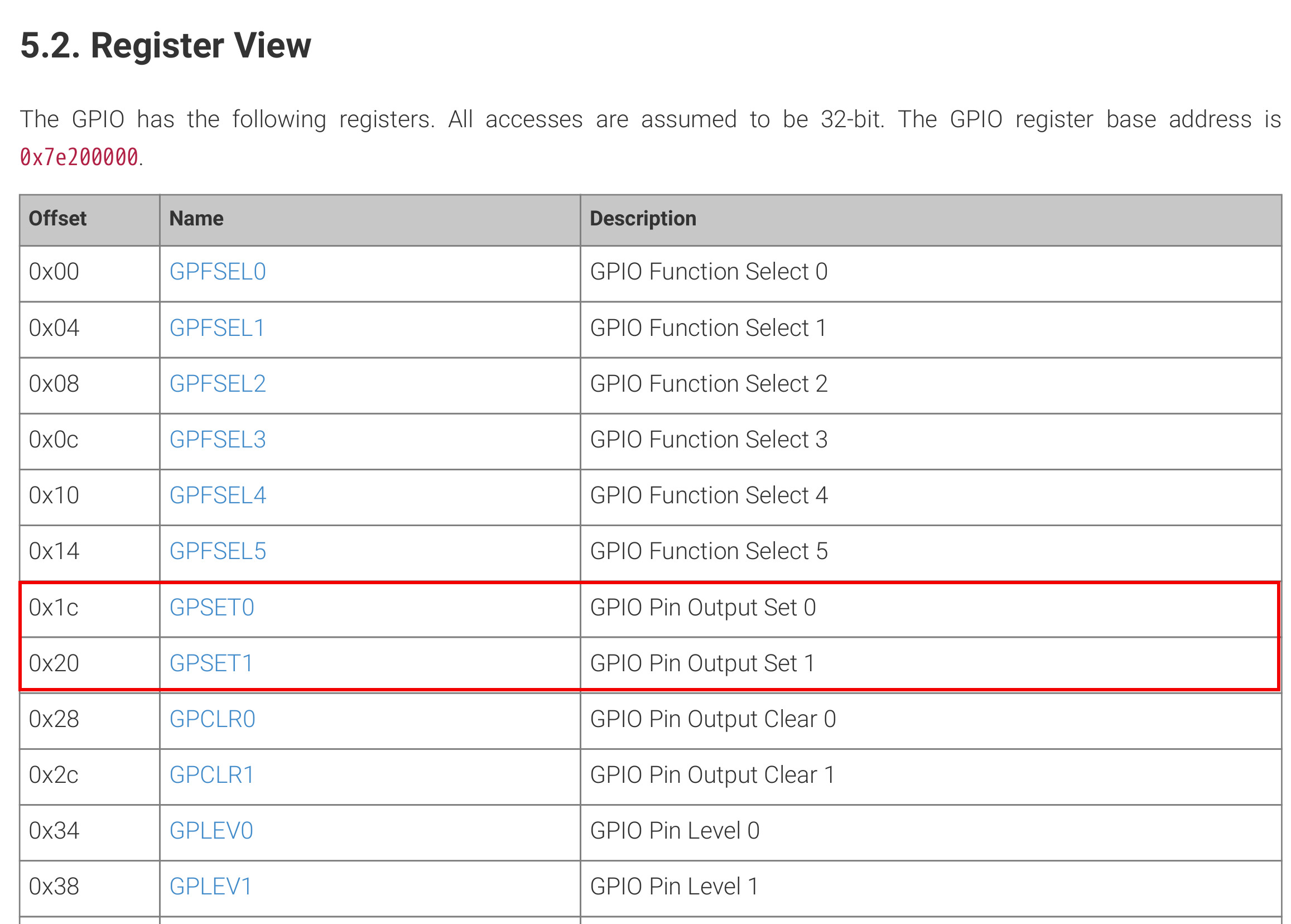
[picture 7] GPSET offset[n]
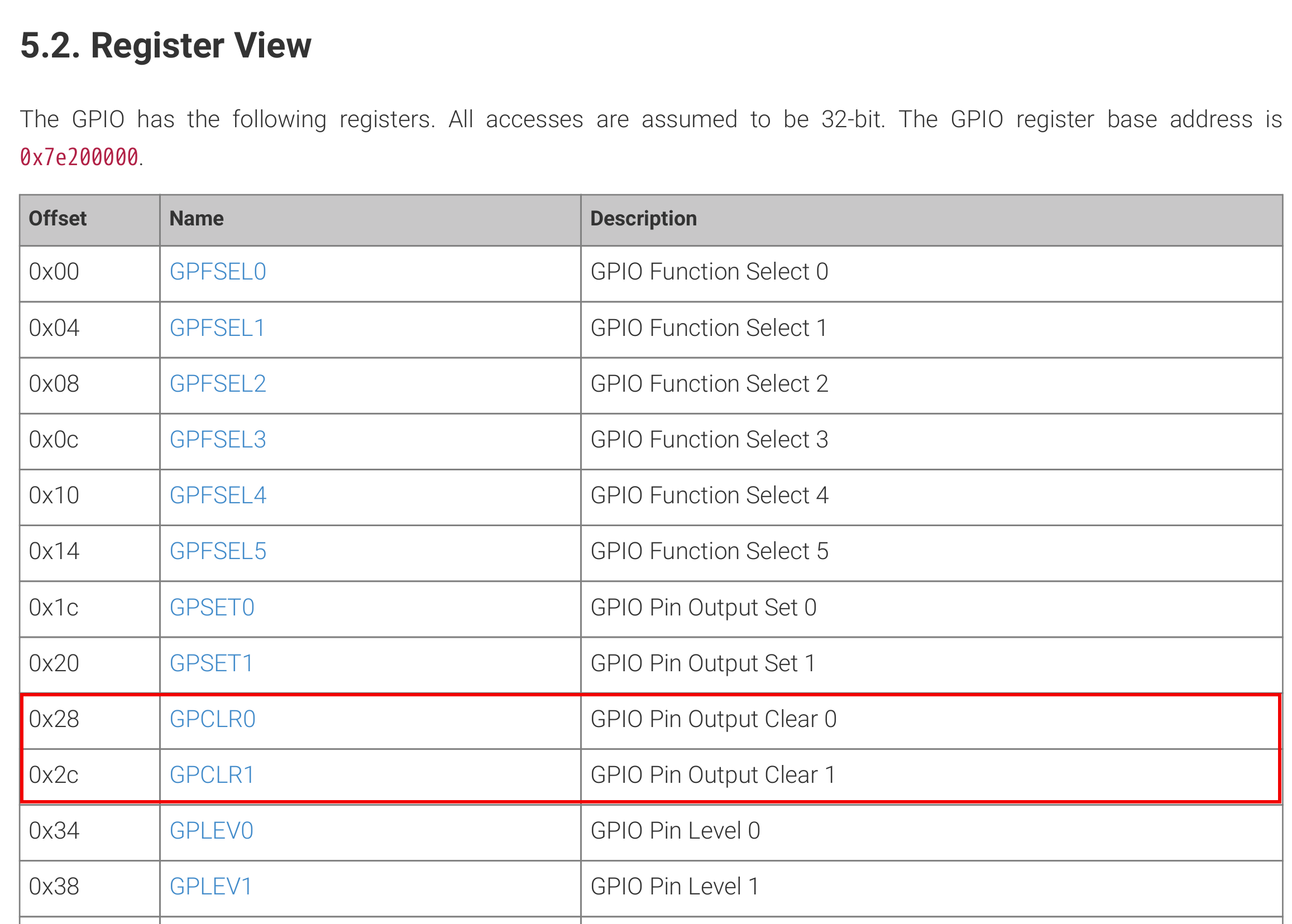
[picture 8] GPCLR offset[n]
At page 70, There are GPSET and GPCLR descriptions.
GPSET’s description

[picture 9] GPSET description
GPCLR’s description

[picture 10] GPCLR description
The mechanism is the same.
General Review
I reviewed some basic functions.
The rest of the functions have the same mechanism.
