
BIGTREETECH EBB42 CAN V1.0 사용하기 klipper firmware 설치
회사 고객 중에서 can 통신 관련해서 이슈가 들어왔습니다.
forum
내용은 EBB42(3D 프린터 부품) 보드를 ODROID-M1과 함께 사용하는 내용이었습니다.


ODROID-M1과 EBB 42 보드
EBB보드는 CAN버스에 물릴 수 있고, odroid-m1은 native can이 지원되기 때문입니다.
호스트 장치, 즉 M1에서 can을 올린 상태에서 진행되는 과정입니다.
CAN을 올리는 방법은 Wiki를 참조하세요.
정리가 좀 필요해서 기록용으로 올립니다.
준비물
- Host PC or ODROID-M1 x1
- EBB42 CAN V1.0 x1
- SN65HVD230 x1
- USB-a to c-type x1
- fan x1 [optional]
EBB42 보드 (CAN V1.0)
EBB 42 보드
EBB 보드입니다.
구매는 여기서 가능하고 공식 레포지토리를 확인할 수 있습니다.
펌웨어는 업로드 날짜(2023-05-10)기준으로 Klipper만 지원합니다.
그래서 이번 주제인 펌웨어 업데이트는 klipper 펌웨어 업데이트 입니다.
제가 가지고 있는 모델은 EBB보드 중에서 EBB42 CAN V1.0 입니다.
버전에 따라서 펌웨어 설정과 업데이트 방법이 다릅니다.
공식 문서 확인하세요.
보드 연결 확인하기
호스트 장치에 usb연결 후 보드 후면에 boot 버튼을 누르면서 전원을 켭니다.
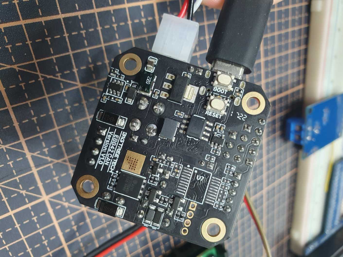
EBB 42 보드 후면
호스트 장치에서 usb 장치가 연결되어 있는지 확인합니다.
$ lsusb
Bus 008 Device 001: ID 1d6b:0003 Linux Foundation 3.0 root hub
Bus 007 Device 014: ID 0483:df11 STMicroelectronics STM Device in DFU Mode
Bus 007 Device 001: ID 1d6b:0002 Linux Foundation 2.0 root hub
Bus 006 Device 001: ID 1d6b:0003 Linux Foundation 3.0 root hub
Bus 005 Device 001: ID 1d6b:0002 Linux Foundation 2.0 root hub
Bus 004 Device 001: ID 1d6b:0001 Linux Foundation 1.1 root hub
Bus 002 Device 001: ID 1d6b:0002 Linux Foundation 2.0 root hub
Bus 003 Device 001: ID 1d6b:0001 Linux Foundation 1.1 root hub
Bus 001 Device 001: ID 1d6b:0002 Linux Foundation 2.0 root hub
연결이 확인 됐으면, 부트로더를 설치합니다.
Klipper 설치하기
Klipper 설치는 부트로더를 사용하는 방법과 사용하지 않는 방법이 있습니다.
이번 포스팅에서는 부트로더를 사용하는 방법을 다뤄보겠습니다.
부트로더를 사용하지 않는 방법은 추후에 SHT_36 보드를 다루게 된다면 포스팅 하겠습니다.
klipper with msc
klipper 를 보드에 플래쉬 하기 전에 부트로더를 먼저 EBB 보드에 설치합니다.
$ git clone https://github.com/Telekatz/MSC-stm32f103-bootloader.git
$ cd MSC-stm32f103-bootloader
$ make MSCboot-STM32F072.bin
$ sudo dfu-util -d 0483:df11 -a 0 -R -D ~/MSC-stm32f103-bootloader/build/MSCboot-STM32F072.bin -s0x08000000:leave
github 소스를 다운받습니다.
$ git clone https://github.com/Klipper3d/klipper
klipper 펌웨어 설정입니다.
$ cd klipper
$ make menuconfig
[*] Enable extra low-level configuration options
    Micro-controller Architecture (STMcroelectronics STM32)
    Processor model (STM32F072)
    Bootloader offset (16KiB bootloader (HID Bootloader))
    Clock Reference (8 MHz crystal)
    Communication interface (CAN bus (on PA8/PA9))
(500000) CAN bus speed
()  GPIO pins to set at micro-controller startup
q를 누르고 Y로 저장 하고 빠져나옵니다.
빌드 실행
$ make
out/klipper.bin이 생성된 것을 확인할 수 있습니다.
펌웨어 설치를 위해 부트로더를 실행 합니다.
부트로더 문서에 활성화 방법이 기술되어 있습니다.
The bootloader can be activated by pressing the reset button of the board twice. As soon as the bootloader is activated,
the board appears as a USB flash drive onto which the klipper.bin file can be copied.
설명대로 후면의 reset 버튼을 두번 누릅니다.
reset 버튼을 두번 누른 후,
저장장치가 파일시스템에 마운트 되는지 확인합니다.
리눅스에서는 fdisk 명령어를 사용합니다.
$ sudo fdisk -l
Disk /dev/mtdblock0: 128 KiB, 131072 bytes, 256 sectors
Units: sectors of 1 * 512 = 512 bytes
Sector size (logical/physical): 512 bytes / 512 bytes
I/O size (minimum/optimal): 512 bytes / 512 bytes


Disk /dev/mtdblock1: 2 MiB, 2097152 bytes, 4096 sectors
Units: sectors of 1 * 512 = 512 bytes
Sector size (logical/physical): 512 bytes / 512 bytes
I/O size (minimum/optimal): 512 bytes / 512 bytes


Disk /dev/mtdblock2: 1 MiB, 1048576 bytes, 2048 sectors
Units: sectors of 1 * 512 = 512 bytes
Sector size (logical/physical): 512 bytes / 512 bytes
I/O size (minimum/optimal): 512 bytes / 512 bytes


Disk /dev/mtdblock3: 12 MiB, 12582912 bytes, 24576 sectors
Units: sectors of 1 * 512 = 512 bytes
Sector size (logical/physical): 512 bytes / 512 bytes
I/O size (minimum/optimal): 512 bytes / 512 bytes


Disk /dev/mmcblk0: 7.29 GiB, 7818182656 bytes, 15269888 sectors
Units: sectors of 1 * 512 = 512 bytes
Sector size (logical/physical): 512 bytes / 512 bytes
I/O size (minimum/optimal): 512 bytes / 512 bytes
Disklabel type: dos
Disk identifier: 0xb2648087

Device         Boot  Start      End  Sectors  Size Id Type
/dev/mmcblk0p1        2048   526335   524288  256M 83 Linux
/dev/mmcblk0p2      526336 15269887 14743552    7G 83 Linux


Disk /dev/sda: 3.93 MiB, 4096000 bytes, 8000 sectors
Disk model: MSC
Units: sectors of 1 * 512 = 512 bytes
Sector size (logical/physical): 512 bytes / 512 bytes
I/O size (minimum/optimal): 512 bytes / 512 bytes
Disklabel type: dos
Disk identifier: 0x00000000
MSC부트로더는 파티션이 따로 존재하지는 않습니다.
klipper를 설치하기 위해(copy & paste) 임의의 디렉토리에 마운트 합니다.
저는 홈에 ebb/ 디렉토리를 만들고 거기에 마운트 하겠습니다.
$ mkdir -p ~/ebb
$ sudo mount /dev/sda ~/ebb
klipper 펌웨어를 설치합니다.
$ sudo cp ~/klipper/out/klipper.bin ~/ebb
$ sync
설치가 끝난 후 연결을 해제 합니다.
$ sudo umount ebb
$ sudo eject /dev/sda
이렇게 펌웨어 설치가 끝났습니다.
klipper with canboot
klipper 를 보드에 플래쉬 하기 전에 부트로더를 먼저 EBB 보드에 설치합니다.
$ git clone https://github.com/Arksine/CanBoot.git
$ cd CanBoot
$ make menuconfig
    Micro-controller Architecture (STMicroelectronics STM32)  --->
    Processor model (STM32F072)  --->
    Build CanBoot deployment application (Do not build)  --->
    Clock Reference (8 MHz crystal)  --->
    Communication interface (CAN bus (on PB8/PB9))  --->
    Application start offset (8KiB offset)  --->
(500000) CAN bus speed
()  GPIO pins to set on bootloader entry
[*] Support bootloader entry on rapid double click of reset button
[ ] Enable bootloader entry on button (or gpio) state
[ ] Enable Status LED
$ make
$ sudo dfu-util -d 0483:df11 -a 0 -R -D ~/CanBoot/out/canboot.bin -s0x08000000:leave
github 소스코드를 다운받습니다.
$ git clone https://github.com/Klipper3d/klipper
klipper 펌웨어 설정입니다.
$ cd klipper
$ make menuconfig
[*] Enable extra low-level configuration options
    Micro-controller Architecture (STMicroelectronics STM32)  --->
    Processor model (STM32F072)  --->
    Bootloader offset (8KiB bootloader)  --->
    Clock Reference (8 MHz crystal)  --->
    Communication interface (CAN bus (on PB8/PB9))  --->
(500000) CAN bus speed
()  GPIO pins to set at micro-controller startup
q를 누르고 Y로 저장 하고 빠져나옵니다.
빌드 실행
$ make
out/klipper.bin이 생성된 것을 확인할 수 있습니다.
펌웨어 설치를 위해 부트로더를 실행 합니다.
부트로더 문서에 활성화 방법이 기술되어 있습니다.
The bootloader can be activated by pressing the reset button of the board twice. As soon as the bootloader is activated,
the board appears as a USB flash drive onto which the klipper.bin file can be copied.
설명대로 후면의 reset 버튼을 두번 누릅니다.
reset 버튼을 두번 누른 후,
klipper에서 CanBoot 전용 스크립트를 실행합니다.
$ python3 ~/klipper/lib/canboot/flash_can.py -i can0 -q
Resetting all bootloader node IDs...
Checking for canboot nodes...
Detected UUID: "your_board's_uuid", Application: CanBoot
Query Complete
$ python3 ~/klipper/lib/canboot/flash_can.py -i can0 -f ~/klipper/out/klipper.bin -u "your_board's_uuid"
Sending bootloader jump command...
Resetting all bootloader node IDs...
Checking for canboot nodes...
Detected UUID: "your_board's_uuid", Application: CanBoot
Attempting to connect to bootloader
CanBoot Connected
Protocol Version: 1.0.0
Block Size: 64 bytes
Application Start: 0x8002000
MCU type: stm32f072xb
Verifying canbus connection
Flashing '/home/odroid/klipper/out/klipper.bin'...

[##################################################]

Write complete: 13 pages
Verifying (block count = 386)...

[##################################################]

Verification Complete: SHA = 1D48AD879FAA421ED337D906BCB949CABB9A1693
CAN Flash Success
이렇게 klipper 펌웨어 업데이트가 끝났습니다.
Klipper 검증하기
새 보드를 사고 새로 펌웨어를 설치하면 보드와 펌웨어 정상동작을 확인해야 합니다.
led를 껐다 켜보는 등 간단한 조작을 해보면 보드 이상과 펌웨어 설치여부를 한번에 확인할 수 있습니다.
저는 EBB42 CAN V1.0의 PA1번 핀과 fan을 연결해 테스트 해보겠습니다.

PA1핀에 fan 연결
klipper 소스를 수정합니다.
커밋: 33b18fd62ba73c90054a7b94b68c341bb3f40d9a 기준입니다.
$ cd ~/klipper/src
$ ls
Kconfig    atsam      basecmd.h    command.h    endstop.c   i2ccmds.c       lcd_hd44780.c  neopixel.c       rp2040      sdiocmds.h        simulator       spicmds.h  thermocouple.c
Makefile   atsamd     buttons.c    compiler.h   generic     i2ccmds.h       lcd_st7920.c   pru              sched.c     sensor_adxl345.c  spi_software.c  stepper.c  tmcuart.c
adccmds.c  avr        byteorder.h  ctr.h        gpiocmds.c  initial_pins.c  linux          pulse_counter.c  sched.h     sensor_angle.c    spi_software.h  stepper.h  trsync.c
ar100      basecmd.c  command.c    debugcmds.c  hc32f460    initial_pins.h  lpc176x        pwmcmds.c        sdiocmds.c  sensor_mpu9250.c  spicmds.c       stm32      trsync.h
gpio를 사용하는 코드를 넣을 것이기 때문에 하드웨어에 종속됩니다.
stm32 디렉토리에 접근 후 코드를 수정합니다.
코드를 수정하고 결과를 보려면 펌웨어가 제얼 먼저 접근하는 main 함수를 먼저 찾습니다.
$ cd stm32
$ git grep main
i2c.c:i2c_read_byte(I2C_TypeDef *i2c, uint32_t timeout, uint8_t remaining)
i2c.c:    if (remaining == 1)
sdio.c:    uint32_t data_remaining = numblocks*blocksize;
sdio.c:            for (uint8_t i=0; (i<4) && (data_remaining>0); i++) {
sdio.c:                data_remaining--;
sdio.c:    while (((sdio->STA & SDIO_STA_RXDAVL) != 0) && (data_remaining > 0)) {
sdio.c:        for (uint8_t i=0; (i<4) && (data_remaining>0); i++) {
sdio.c:            data_remaining--;
sdio.c:    uint32_t data_remaining = numblocks*blocksize;
sdio.c:            for (uint8_t i=0; (i<4) && (data_remaining>0); i++) {
sdio.c:                data_remaining--;
spi.c:    // Wait for any remaining SCLK updates before returning
stm32f0.c:#include "board/armcm_boot.h" // armcm_main
stm32f0.c:#include "sched.h" // sched_main
stm32f0.c:armcm_main(void)
stm32f0.c:    // Configure main clock
stm32f0.c:    sched_main();
stm32f1.c:#include "sched.h" // sched_main
stm32f1.c:armcm_main(void)
stm32f1.c:    sched_main();
stm32f4.c:#include "sched.h" // sched_main
stm32f4.c:armcm_main(void)
stm32f4.c:    sched_main();
stm32f7.c:#include "sched.h" // sched_main
stm32f7.c:armcm_main(void)
stm32f7.c:    sched_main();
stm32g0.c:#include "board/armcm_boot.h" // armcm_main
stm32g0.c:#include "sched.h" // sched_main
stm32g0.c:armcm_main(void)
stm32g0.c:    // Configure main clock
stm32g0.c:    sched_main();
stm32g4.c:#include "sched.h" // sched_main
stm32g4.c:armcm_main(void)
stm32g4.c:    sched_main();
stm32h7.c:#include "sched.h" // sched_main
stm32h7.c:armcm_main(void)
stm32h7.c:    sched_main();
stm32l4.c:#include "sched.h" // sched_main
stm32l4.c:armcm_main(void)
stm32l4.c:    sched_main();
usbotg.c:    usb_notify_ep0(); // XXX - wake from main usb_cdc.c code?
EBB42보드는 stm32f072를 사용하기 때문에
stm32f0.c를 확인 합니다.
$ vi stm32f0.c
165 // Main entry point - called from armcm_boot.c:ResetHandler()
166 void
167 armcm_main(void)
168 {
169     dfu_reboot_check();
170     SystemInit();
171
172     enable_pclock(SYSCFG_BASE);
173     if (CONFIG_ARMCM_RAM_VECTORTABLE)
174         enable_ram_vectortable();
175
176     // Set flash latency
177     FLASH->ACR = (1 << FLASH_ACR_LATENCY_Pos) | FLASH_ACR_PRFTBE;
178
179     // Configure main clock
180     if (CONFIG_MACH_STM32F0x2 && CONFIG_STM32_CLOCK_REF_INTERNAL && CONFIG_USB)
181         hsi48_setup();
182     else
183         pll_setup();
184
185     // Turn on hsi14 oscillator for ADC
186     hsi14_setup();
187
188     // Support pin remapping USB/CAN pins on low pinout stm32f042
189 #ifdef SYSCFG_CFGR1_PA11_PA12_RMP
190     if (CONFIG_STM32_USB_PA11_PA12_REMAP || CONFIG_STM32_CANBUS_PA11_PA12_REMAP)
191         SYSCFG->CFGR1 |= SYSCFG_CFGR1_PA11_PA12_RMP;
192 #endif
193
194     sched_main();
195 }
194번 라인 sched_main 함수가 스케줄링 함수인 것을 유추 가능합니다.
펌웨어와 보드가 정상동작하는지 확인하기 위해 PA1번 핀을 on/off 할 것이고,
스케줄링이 시작되기 전에 loop문으로 스케줄링을 막고 확인하겠습니다.
다시 빠져나와서 gpio write 관련 함수를 찾습니다
:q
gpio 관련 함수는 하드웨어에 종속될 수도 있고 아닐 수도 있습니다.
write동작은 generic하게 구현하고 메모리 주소를 각 하드웨어 헤더파일에 선언할 수 있으니까요.
$ cd ..
$ git grep gpio
...
gpiocmds.c:#include "board/gpio.h" // struct gpio_out
gpiocmds.c:    struct gpio_out pin;
gpiocmds.c:    gpio_out_toggle_noirq(d->pin);
gpiocmds.c:    gpio_out_write(d->pin, flags);
gpiocmds.c:    struct gpio_out pin = gpio_out_setup(args[1], !!args[2]);
gpiocmds.c:    gpio_out_write(d->pin, on_flag);
gpiocmds.c:        gpio_out_write(d->pin, d->flags & DF_DEFAULT_ON);
gpiocmds.c:    gpio_out_setup(args[0], args[1]);
...
grep 결과 중에 api로 추정되는 부분을 찾았습니다.
확인해 볼 만한 것은 board/gpio.h , gpio_out , gpio_out_write , gpio_out_setup 정도 입니다.
이번에는 이 함수들이 어떻게 정의되어 있고 사용되는지 보기 위해 하위 폴더에서 grep으로 다시 필터링 합니다.
$ cd stm32
$ git grep gpio_out
gpio.c:#include "gpio.h" // gpio_out_setup
gpio.c:struct gpio_out
gpio.c:gpio_out_setup(uint32_t pin, uint32_t val)
gpio.c:    struct gpio_out g = { .regs=regs, .bit=GPIO2BIT(pin) };
gpio.c:    gpio_out_reset(g, val);
gpio.c:gpio_out_reset(struct gpio_out g, uint32_t val)
gpio.c:gpio_out_toggle_noirq(struct gpio_out g)
gpio.c:gpio_out_toggle(struct gpio_out g)
gpio.c:    gpio_out_toggle_noirq(g);
gpio.c:gpio_out_write(struct gpio_out g, uint32_t val)
gpio.h:struct gpio_out {
gpio.h:struct gpio_out gpio_out_setup(uint32_t pin, uint32_t val);
gpio.h:void gpio_out_reset(struct gpio_out g, uint32_t val);
gpio.h:void gpio_out_toggle_noirq(struct gpio_out g);
gpio.h:void gpio_out_toggle(struct gpio_out g);
gpio.h:void gpio_out_write(struct gpio_out g, uint32_t val);
usbfs.c:#include "board/gpio.h" // gpio_out_setup
usbfs.c:        gpio_out_setup(GPIO('A', 12), 0);
gpio_out 관련 함수들을 사용하려면 gpio.h 헤더가 필요하고,
마지막 줄에 있는 부분은 실제로 gpio_out_setup을 사용하고 있습니다.
$ vi usbfs.c
336 // Initialize the usb controller
337 void
338 usb_init(void)
339 {
340     if (CONFIG_MACH_STM32F1) {
341         // Pull the D+ pin low briefly to signal a new connection
342         gpio_out_setup(GPIO('A', 12), 0);
343         udelay(5000);
344         gpio_in_setup(GPIO('A', 12), 0);
345     }
346
347     // Enable USB clock
348     enable_pclock(USB_BASE);
349
350     // Setup USB packet memory
351     btable_configure();
352
353     // Enable USB pullup
354 #ifdef USB_BCDR_DPPU
355     USB->BCDR = USB_BCDR_DPPU;
356 #endif
357
358     // Reset usb controller and enable interrupts
359     USB->CNTR = USB_CNTR_FRES;
360     USB->DADDR = 0;
361     USB->CNTR = USB_CNTR_RESETM;
362     USB->ISTR = 0;
363     armcm_enable_irq(USB_IRQHandler, USBx_IRQn, 1);
364 }
365 DECL_INIT(usb_init);
usb초기화 함수입니다.
gpio_out_setup(GPIO(‘A’, 12), 0); 함수를 보면
PA12번 핀을 out으로 셋업하는 것 같습니다.
뒤에 숫자 0은 uint32_t val인데 의미는 모르겠습니다.
값을 토글해서 의미를 찾겠습니다.
소스를 수정해서 펌웨어를 업데이트 하겠습니다.
$ vi ~/klipper/src/stm32/stm32f0.c
   1 // Code to setup clocks on stm32f0
   2 //
   3 // Copyright (C) 2019-2021  Kevin O'Connor <kevin@koconnor.net>
   4 //
   5 // This file may be distributed under the terms of the GNU GPLv3 license.
   6
   7 #include "autoconf.h" // CONFIG_CLOCK_REF_FREQ
   8 #include "board/armcm_boot.h" // armcm_main
   9 #include "board/armcm_reset.h" // try_request_canboot
  10 #include "board/irq.h" // irq_disable
  11 #include "board/misc.h" // bootloader_request
  12 #include "command.h" // DECL_CONSTANT_STR
  13 #include "internal.h" // enable_pclock
  14 #include "sched.h" // sched_main
+ 15 #include "gpio.h"

...

  165 // Main entry point - called from armcm_boot.c:ResetHandler()
  166 void
  167 armcm_main(void)
  168 {
  169     dfu_reboot_check();
  170     SystemInit();
  171
  172     enable_pclock(SYSCFG_BASE);
  173     if (CONFIG_ARMCM_RAM_VECTORTABLE)
  174         enable_ram_vectortable();
  175
  176     // Set flash latency
  177     FLASH->ACR = (1 << FLASH_ACR_LATENCY_Pos) | FLASH_ACR_PRFTBE;
  178
  179     // Configure main clock
  180     if (CONFIG_MACH_STM32F0x2 && CONFIG_STM32_CLOCK_REF_INTERNAL && CONFIG_USB)
  181         hsi48_setup();
  182     else
  183         pll_setup();
  184
  185     // Turn on hsi14 oscillator for ADC
  186     hsi14_setup();
  187
+ 188     while (1) {
+ 189         gpio_out_setup(GPIO('A', 1), 0);
+ 190         for (int i = 0; i <= 100000; i++);
+ 191         gpio_out_setup(GPIO('A', 1), 1);
+ 192         for (int i = 0; i <= 100000; i++);
+ 193     }
+ 194
  195     // Support pin remapping USB/CAN pins on low pinout stm32f042
  196 #ifdef SYSCFG_CFGR1_PA11_PA12_RMP
  197     if (CONFIG_STM32_USB_PA11_PA12_REMAP || CONFIG_STM32_CANBUS_PA11_PA12_REMAP)
  198         SYSCFG->CFGR1 |= SYSCFG_CFGR1_PA11_PA12_RMP;
  199 #endif
  200
  201     sched_main();
  202 }
딜레이함수는 for문으로 대체했습니다. 찾기 귀찮기도 하고
펌웨어 빌드합니다. config는 전단계와 같아서 생략해도 됩니다.
$ cd ~/klipper
$ make clean
$ make
업데이트는 위와 똑같이 리셋 2번, 장치 마운트 후 진행하면 됩니다.
중간과정 생략합니다.
$ sudo cp ~/klipper/out/klipper.bin ~/ebb
$ sync
$ sudo umount ~/ebb
결과는 다음과 같습니다.

이렇게 펌웨어와 보드 동작을 검증했습니다.
gpio_out_setup은 GPIO를 OUTPUT모드로 초기화 하는 함수 같습니다.
파라미터로 들어가는 숫자 0의 의미를 찾기위해 loop에서 토글했지만 차이는 모르겠네요.
검증이 끝나면 소스를 되돌리고 다시 업데이트 하면 됩니다.
요약
 1. 준비물 확인
 2. 호스트장치(PC or odroid-m1)과 EBB42 보드를 usb로 연결
 3. 호스트 장치, EBB42 power on (EBB보드는 boot 버튼을 누르면서)
 4. lsusb로 호스트 장치에서 EBB 보드가 DFU모드로 붙었는지 확인
 5. MSC bootloader 소스코드 설치 & 빌드
 6. dfu-util 명령어로 MSC bootloader 설치
 7. klipper 소스코드 설치 & 빌드
 8. EBB42 보드 reset 버튼을 2번 눌러서(모드 변경) 메모리를 호스트 파일 시스템에 마운트
 9. fdisk로 메모리 노드 확인
10. EBB42 메모리를 호스트 파일시스템의 임의의 디렉토리에 마운트하고 klipper.bin 파일 복사
11. EBB42 & klipper 검증
12. klipper 원복 후 펌웨어 업데이트
참고 문서
klipper 설치 이후
3d프린터에 연결해서 동작 확인이랑 디버깅 정도 할 것 같습니다.

Leave a comment